- 您现在的位置:买卖IC网 > Sheet目录331 > IR11682STRPBF (International Rectifier)IC MOSFET DRIVER DUAL 200V 8SOIC
IR11682S
Application Information and Additional Details
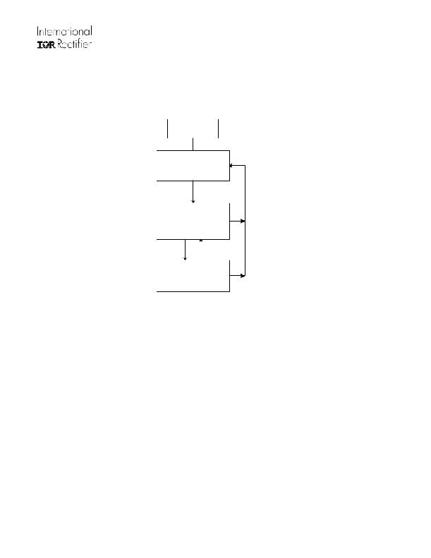
State Diagram
POWER ON
Gate Inactive
UVLO MODE
VCC < VCCon
Gate Inactive
I CC = I CC START
VCC > VCCon
& V DS >V TH3
VCC < VCCuvlo
NORMAL
Gate Active
Gate PW ≥ MOT
Cycle by Cycle MOT Check Enabled
V DS >V TH1 @ MOT
V DS <V TH1 @ MOT
MOT PROTECTION
MODE
Gate Output Disabled
UVLO Mode:
The IC is in the UVLO mode when the VCC pin voltage is below VCCUVLO. The UVLO mode is accessible
from any other state of operation. In the UVLO state, most of the internal circuitry is unbiased and the IC
draws a quiescent current of ICCSTART.
The IC remains in the UVLO condition until the voltage on the VCC pin exceeds the VCC turn on threshold
voltage, VCC ON.
Normal Mode:
Once Vcc exceeds the UVLO voltage, the IC is ready to go into Normal mode. The GATE outputs are
activated when the VDS sensed on the MOSFET crosses VTH3. This function will prevent the GATE to turn-
on towards the end of a switching cycle and prevent reverse current in MOT time. In Normal mode the gate
drivers are operating and the IC will draw a maximum of ICC from the supply voltage source.
MOT Protection Mode
If the secondary current conduction time is shorter than the MOT (Minimum On Time) time, the next driver
output is disabled. This function can avoid reverse current that occurs when the system works at very light/no
load conditions and reduce system standby power consumption by disabling GATE outputs. The IC
automatically goes back to normal operation mode once the load increases to a level and the secondary
current conduction time is longer than MOT.
www.irf.com
12
? 2010 International Rectifier
发布紧急采购,3分钟左右您将得到回复。
相关PDF资料
IR1168SPBF
IC MOSFET DRIVER DUAL 200V 8SOIC
IR1176STR
IC DRIVER RECT SYNC 5V 4A 20SSOP
IR2010SPBF
IC DRIVER HIGH/LOW SIDE 16SOIC
IR2011PBF
IC DRIVER HIGH/LOW SIDE 8-DIP
IR20153STRPBF
IC DRIVER HI SIDE RECHARGE 8SOIC
IR2086STRPBF
IC DRIVER FULL BRIDGE 16-SOIC
IR2101PBF
IC DRIVER HIGH/LOW SIDE 8DIP
IR2103SPBF
IC DRIVER HALF BRIDGE 600V 8SOIC
相关代理商/技术参数
IR1168S
制造商:IRF 制造商全称:International Rectifier 功能描述:DUAL SMART RECTIFIER DRIVER IC
IR1168SPBF
功能描述:开关变换器、稳压器与控制器 200V DUAL SMART HI SPEED SR CTRLLER RoHS:否 制造商:Texas Instruments 输出电压:1.2 V to 10 V 输出电流:300 mA 输出功率: 输入电压:3 V to 17 V 开关频率:1 MHz 工作温度范围: 安装风格:SMD/SMT 封装 / 箱体:WSON-8 封装:Reel
IR1168SPBF
制造商:International Rectifier 功能描述:Smart Rectifier Driver IC
IR1168STRPBF
功能描述:开关变换器、稳压器与控制器 Dual Smartrectifier Drvr IC RoHS:否 制造商:Texas Instruments 输出电压:1.2 V to 10 V 输出电流:300 mA 输出功率: 输入电压:3 V to 17 V 开关频率:1 MHz 工作温度范围: 安装风格:SMD/SMT 封装 / 箱体:WSON-8 封装:Reel
IR1169S
制造商:IRF 制造商全称:International Rectifier 功能描述:ADVANCED SMARTRECTIFIER CONTROL IC
IR1169SPBF
功能描述:功率驱动器IC ADV SmartRectifier 200V 10.7V 70ns
RoHS:否 制造商:Micrel 产品:MOSFET Gate Drivers 类型:Low Cost High or Low Side MOSFET Driver 上升时间: 下降时间: 电源电压-最大:30 V 电源电压-最小:2.75 V 电源电流: 最大功率耗散: 最大工作温度:+ 85 C 安装风格:SMD/SMT 封装 / 箱体:SOIC-8 封装:Tube
IR1169STRPBF
功能描述:功率驱动器IC ADV SmartRectifier 200V 10.7V 70ns RoHS:否 制造商:Micrel 产品:MOSFET Gate Drivers 类型:Low Cost High or Low Side MOSFET Driver 上升时间: 下降时间: 电源电压-最大:30 V 电源电压-最小:2.75 V 电源电流: 最大功率耗散: 最大工作温度:+ 85 C 安装风格:SMD/SMT 封装 / 箱体:SOIC-8 封装:Tube
IR1175
制造商:IRF 制造商全称:International Rectifier 功能描述:Synchronous Rectifier Driver
